Geometries
Geometry Description
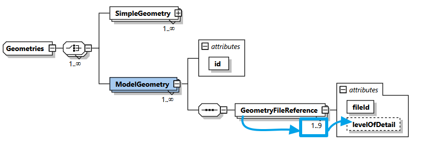
Geometries is the ninth child-element of GeneralDefinitions - the part in the XML where global and reusable elements are defined (imagine them as the building blocks of each luminaire). The definition of Geometries is optional.
Location in XSD
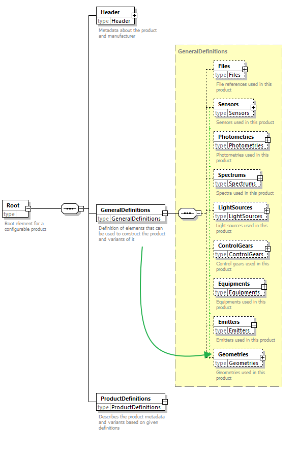
XSD description
In GLDF, geometries for a luminaire can be defined in two ways:
- Basic geometries by using the
SimpleGeometryelement. These are limited to cuboid and cylinder only. However, they have the advantage of being specified directly in the GLDF XML. Simple geometries should be primarily used to overwrite the geometry definition inside the photometry file, should this be required for any reason. - Complex 3D models using the
ModelGeometryelement. 3D models are always located in external files and referenced in the GLDF like otherFilesin previous chapters.
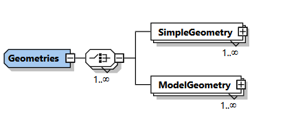
Per GLDF multiple SimpleGeometry and ModelGeometry elements can be defined. However, this should not be often the case, as Variants which differ even in their geometry should presumably represent independent products with own GLDF files.
SimpleGeometry element
A SimpleGeometry corresponds to the descriptions known from the photometric format Eulumdat. Where the luminaire can be a rectangular box or a cylinder either. The definition of a simple geometry inside GLDF allows to override this photometry geometry. At least if necessary - there is no mandatory requirement to define a simple geometry (or any geometry) for your luminaire at all.
Beside the mandatory id attribute to reference the Geometry later, two additional elements (including their childs) and one optional element has to be specified for each SimpleGeometry:
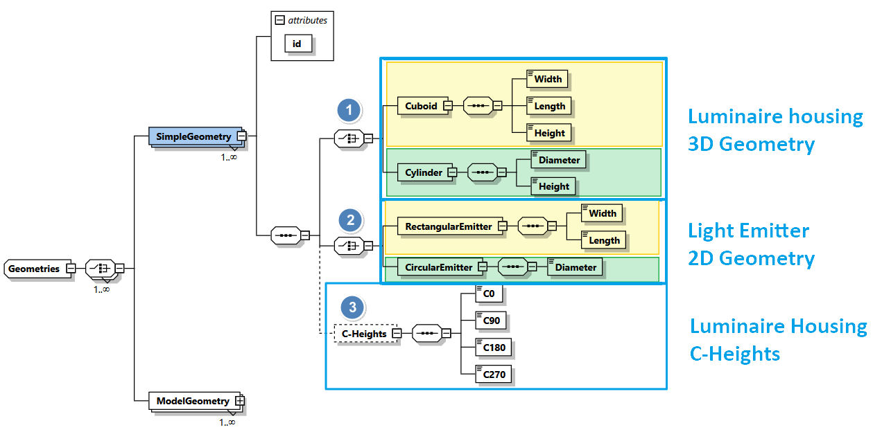
- The luminaire housing (3d body)
- Either
CuboidwithWidth,LengthandHeight - Or
CylinderwithDiameterandHeight
- Either
- The light emitting surface (2d surface)
- Either rectangular shaped with its
WidthandLength - Or circular shaped with
Diameter
- Either rectangular shaped with its
- Optionally C-Heights of the housing
- For C0, C90, C180 and C270
SimpleGeometry example
In the following example, we create a luminaire that references a ChangeableLightEmitter with an associated Photometry. We also define a SimpleGeometry which is to be used instead of the geometry definition inside the Eulumdat photometry. This way, all photometric information comes from the .ldt photometry file. But not the geometry for visualising the casing of the luminaire:
<?xml version="1.0" encoding="UTF-8"?>
<Root xmlns:xsi="http://www.w3.org/2001/XMLSchema-instance"
      xsi:noNamespaceSchemaLocation="https://gldf.io/xsd/gldf/1.0.0-rc.3/gldf.xsd">
  <Header>
    <Manufacturer>ACME Lighting</Manufacturer>
    <FormatVersion major="1" minor="0" pre-release="3" />
    <CreatedWithApplication>Visual Studio Code</CreatedWithApplication>
    <GldfCreationTimeCode>2023-10-25T16:30:00Z</GldfCreationTimeCode>
    <UniqueGldfId>56a1abed-8c56-4902-8b83-616abe706f37</UniqueGldfId>
  </Header>
  <GeneralDefinitions>
    <Files>
      <File id="ldtFile" contentType="ldc/eulumdat"
            type="localFileName">photometry.ldt</File>
    </Files>
    <Photometries>
      <Photometry id="photometry">
        <PhotometryFileReference fileId="ldtFile" />
      </Photometry>
    </Photometries>
    <Emitters>
      <Emitter id="emitter">
        <ChangeableLightEmitter>
          <PhotometryReference photometryId="photometry" />
        </ChangeableLightEmitter>
      </Emitter>
    </Emitters>
    <Geometries>
      <SimpleGeometry id="geometry">
        <Cuboid>
          <Width>100</Width>
          <Length>200</Length>
          <Height>50</Height>
        </Cuboid>
        <RectangularEmitter>
          <Width>50</Width>
          <Length>100</Length>
        </RectangularEmitter>
      </SimpleGeometry>
    </Geometries>
  </GeneralDefinitions>
  <ProductDefinitions>
    <ProductMetaData>
      <UniqueProductId>f06e1025-41a6-4b32-a9ad-3fa3c49ba473</UniqueProductId>
      <ProductNumber>
        <Locale language="en">42</Locale>
      </ProductNumber>
      <Name>
        <Locale language="en">Example luminaire</Locale>
      </Name>
    </ProductMetaData>
    <Variants>
      <Variant id="variant">
        <Name>
          <Locale language="en">Example luminaire</Locale>
        </Name>
        <Geometry>
          <SimpleGeometryReference geometryId="geometry" emitterId="emitter" />
        </Geometry>
      </Variant>
    </Variants>
  </ProductDefinitions>
</Root>
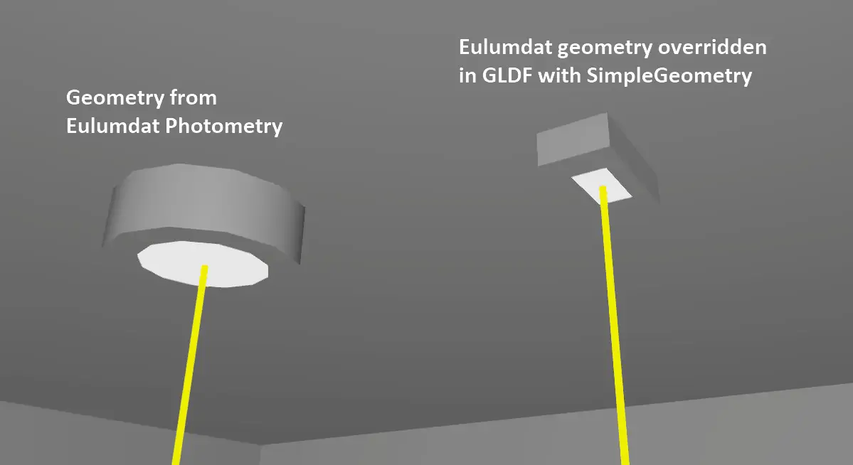
The following image depicts, how an SimpleGeometry affects visualisation.
- On the left side, a GLDF in DIALux is rendered with a cylindric geometry from the Eulumdat file. Without any
Geometriesdefinition at all. - On the right, the same GLDF is visualized, but this time with a
SimpleGeometryfrom the XML example above. To override the cylindric Eulumdat geometry with a cubic one. Although this is a constructed example, it illustrates the use case ofSimpleGeometry.
ModelGeometry element
The definition of a ModelGeometry consists of two steps:
- First, the corresponding 3D file must be stored in the subfolder geo and made referenceable in the GLDF as
Fileelement via itsidattribute. - Second, a
ModelGeometryelement must be created, which has only one further child element:GeometryFileReference- which references the 3D geometry file from the first step. See example below.
How to create 3D models is described in own chapters:
- Would you like to read more about the new L3D file format? Have a look on the L3D Introduction.
- Would you like to start creating L3D models, check out our L3D Editor
ModelGeometry example
<?xml version="1.0" encoding="UTF-8"?>
<Root xmlns:xsi="http://www.w3.org/2001/XMLSchema-instance"
      xsi:noNamespaceSchemaLocation="https://gldf.io/xsd/gldf/1.0.0-rc.3/gldf.xsd">
  <Header>
    <Manufacturer>ACME Lighting</Manufacturer>
    <FormatVersion major="1" minor="0" pre-release="3" />
    <CreatedWithApplication>Visual Studio Code</CreatedWithApplication>
    <GldfCreationTimeCode>2023-10-25T16:30:00Z</GldfCreationTimeCode>
    <UniqueGldfId>56a1abed-8c56-4902-8b83-616abe706f37</UniqueGldfId>
  </Header>
  <GeneralDefinitions>
    <Files>
      <File id="ldtFile" contentType="ldc/eulumdat"
            type="localFileName">photometry.ldt</File>
      <File id="geometryFile" contentType="geo/l3d"
            type="localFileName">geometry.l3d</File>
    </Files>
    <Photometries>
      <Photometry id="photometry">
        <PhotometryFileReference fileId="ldtFile" />
      </Photometry>
    </Photometries>
    <Emitters>
      <Emitter id="emitter">
        <ChangeableLightEmitter>
          <PhotometryReference photometryId="photometry" />
        </ChangeableLightEmitter>
      </Emitter>
    </Emitters>
    <Geometries>
      <ModelGeometry id="geometry">
        <GeometryFileReference fileId="geometryFile" />
      </ModelGeometry>
    </Geometries>
  </GeneralDefinitions>
  <ProductDefinitions>
    <ProductMetaData>
      <UniqueProductId>f06e1025-41a6-4b32-a9ad-3fa3c49ba473</UniqueProductId>
      <ProductNumber>
        <Locale language="en">42</Locale>
      </ProductNumber>
      <Name>
        <Locale language="en">Example luminaire</Locale>
      </Name>
    </ProductMetaData>
    <Variants>
      <Variant id="variant">
        <Name>
          <Locale language="en">Example luminaire</Locale>
        </Name>
        <Geometry>
          <ModelGeometryReference geometryId="geometry">
            <EmitterReference emitterId="emitter">
              <EmitterObjectExternalName>leo</EmitterObjectExternalName>
            </EmitterReference>
          </ModelGeometryReference>
        </Geometry>
      </Variant>
    </Variants>
  </ProductDefinitions>
</Root>
Level of detail
GeometryFileReference contains one more interesting attribute: levelOfDetail. This attribute explains why the probably confusing multiplicity of 1..9 for GeometryFileReference is defined. Which means that 1 to 9 elements of the GeometryFileReference type can be added to each ModelGeometry.
The attribute levelOfDetail allows applications to choose and display the 3D models in three different level of detail. This can be useful depending on the use case. A lighting planner may need a detailed model for his customer. While in the further BIM process a simplified representation is sufficient. The possible values are:
lowmediumhigh
As GLDF supports 3 model file types (l3d, m3d, r3d). And there are three level of detail for each. You can reference up to 9 files (and thus 9 GeometryFileReference elements) inside each ModelGeometry.
<Geometries>
  <ModelGeometry id="geometry-With-LevelOfDetail">
    <GeometryFileReference fileId="geometryFile-low" levelOfDetail="Low" />
    <GeometryFileReference fileId="geometryFile-medium" levelOfDetail="Medium" />
    <GeometryFileReference fileId="geometryFile-high" levelOfDetail="High" />
  </ModelGeometry>
</Geometries>
Referencing a geometry
Once declared, all geometries can be referenced in subsequent XML elements via their id attribute one or several times. This is done in the Variant element and described in detail here.