Emitters
Emitter Description
Emitters is the eighth child-element of GeneralDefinitions - the part in the XML where global and reusable elements are defined (imagine them as the building blocks of each luminaire).
Emitters define the radiation emitting parts of the luminaire. Be it in form of visible light of lamps or infrared EMR in case of motion detection sensors. However, they define not the lamps or sensors themselves. Emitters is the XML block, where many of these parts before come together. They are the parts of the luminaire description, where the measured photometry is finally placed. And get combined later in Variants with the geometrical definition of the luminaire:
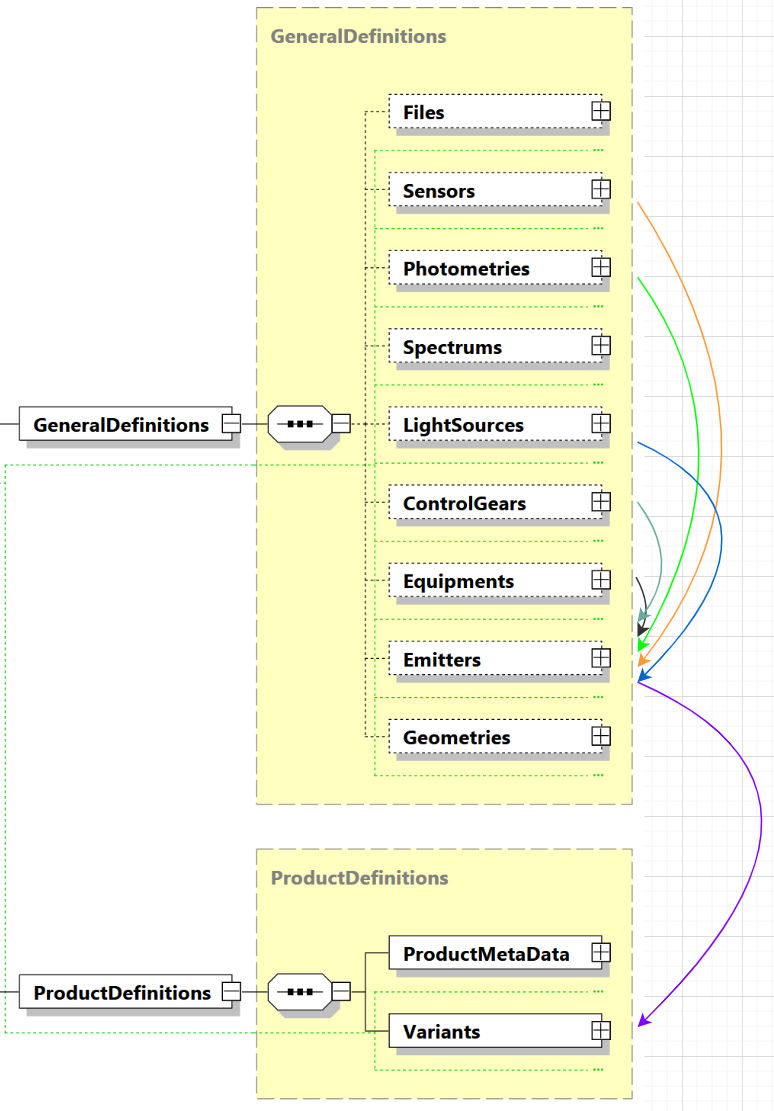
Emitter root element
First of all you have to decide which type of emitter is required for your radiation emitting part. Each luminaire can contain multiple Emitter with different types. The following four types are available:
- Emitter for a lamp that can be replaced in the luminaire ➜ choose
ChangeableLightEmitter - Emitter for a lamp permanently installed in the luminaire ➜ choose
FixedLightEmitter - Emitter for a multi channel light source in the luminaire ➜ choose
MultiChannelLightEmitter - Emitter for a sensor ➜ choose
SensorEmitter
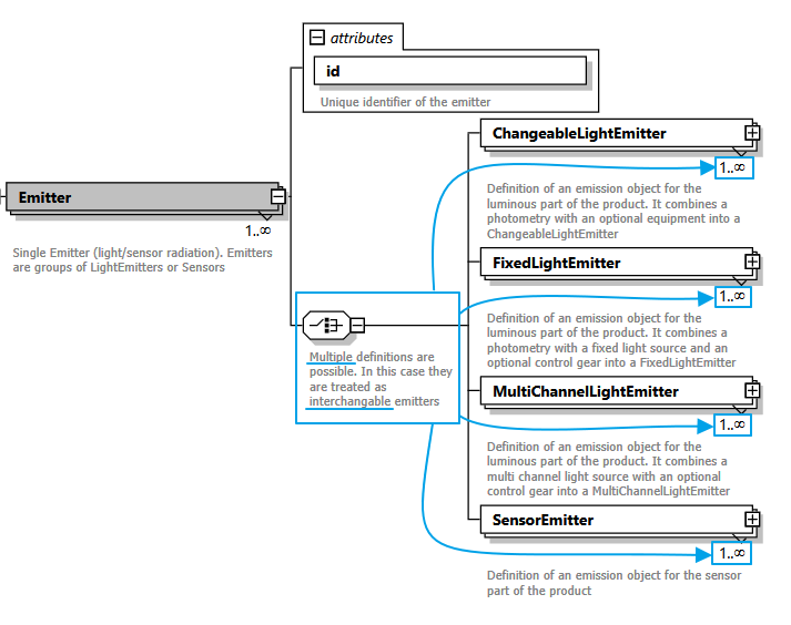
One remarkable part of the XSD definition above is the fact, that GLDF accepts one or more ChangeableLightEmitter for each single Emitter. Or one or more FixedLightEmitter, MultiChannelLightEmitter or Sensor vice versa.
This does not mean that all these emitters are active simultaneously. Instead, they are interchangeable. The luminaire can operate in only one of these modes. Users in lighting calculation software, such as DIALux or RELUX, can switch between these modes as needed.
Examples
Example #1: Imagine a luminaire with emergency mode on one light source. In GLDF you can describe this with one emitter which contains two ChangeableLightEmitter child elements. One for normal mode and e.g. 500 lumen and another ChangeableLightEmitter for the same light output, but with emergency mode and 50 lumen. Both are not active at the same time but can operate in one mode or another.
Example #2: Imagine a luminaire measured/sold with two different lamps (and therefore probably different lighting, spectrum and electric characteristics). Again, you can describe this use case with multiple Equipments referenced inside one Emitter. This way they are meant to be interchangeable, rather than both active at same time on multiple light outputs.
Let's assume we would like to define a luminaire with a changeable light output. So for the moment a first Emitter XML example could look as follows:
<?xml version="1.0" encoding="UTF-8"?>
<Root xmlns:xsi="http://www.w3.org/2001/XMLSchema-instance">
  <Header/>
  <GeneralDefinitions>
    <!-- Content skipped for clarity -->
    <Emitters>
      <Emitter id="emitter1">
        <ChangeableLightEmitter>
          <!-- Changeable Emitter content skipped for now -->
        </ChangeableLightEmitter>
      </Emitter>
    </Emitters>
  </GeneralDefinitions>
  <ProductDefinitions/>
</Root>
ChangeableLightEmitter
An Emitter with child element(s) of type ChangeableLightEmitter is intended for light outputs with changeable lamps, as the name already says. Another functionality is to map multiple emergency modes or different control gears for one light output. All this variability can be achieved with this type. Choose the ChangeableLightEmitter as well, if you have defined Equipments previously (a combination of ChangeableLightSource with optional ControlGear). And you would like to reference them now.
XSD description
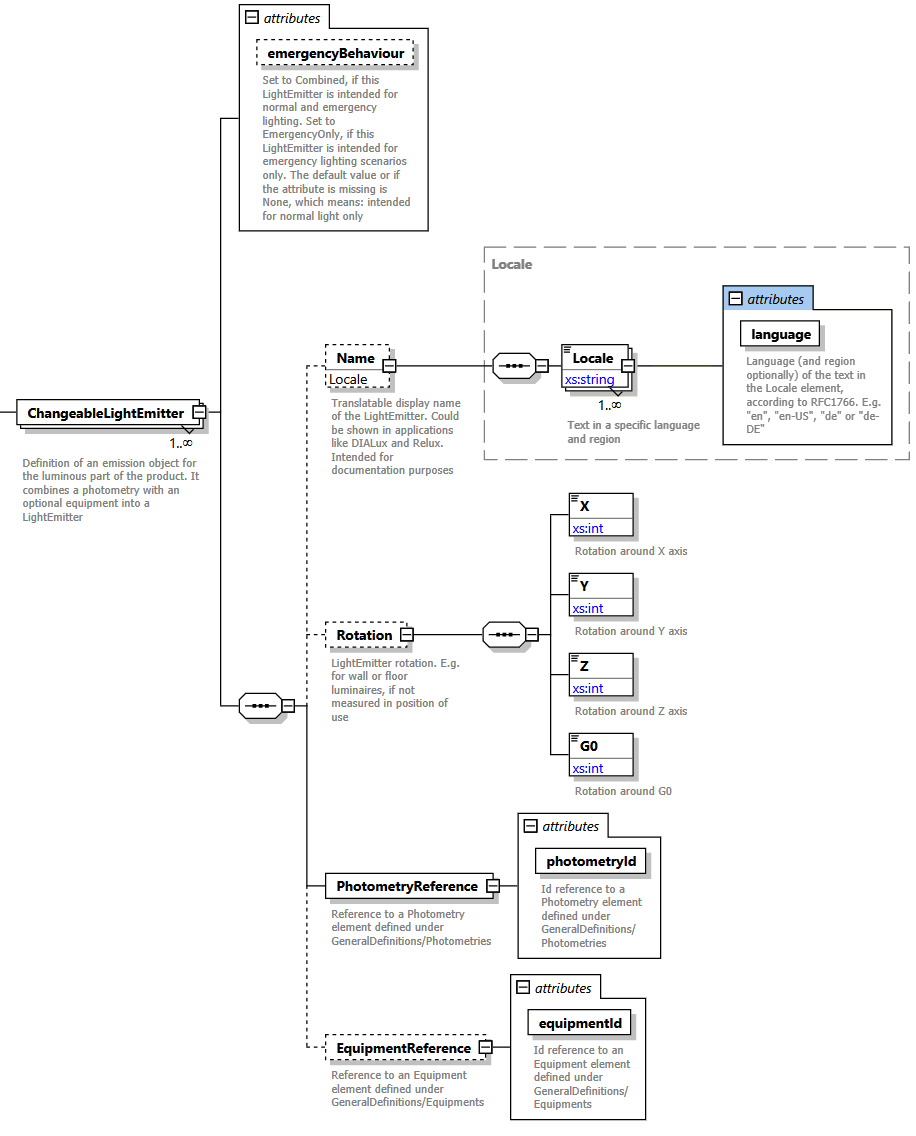
The only required element of a ChangeableLightEmitter is a PhotometryReference to define the light distribution curve of this light emitter. Let's expand the example to it in line 16:
<?xml version="1.0" encoding="UTF-8"?>
<Root xmlns:xsi="http://www.w3.org/2001/XMLSchema-instance">
  <Header/>
  <GeneralDefinitions>
    <Files>
      <File id="eulumdatNarrow" contentType="ldc/eulumdat" type="localFileName">50W_Narrow.ldt</File>
    </Files>
    <Photometries>
      <Photometry id="photometryNarrow">
        <PhotometryFileReference fileId="eulumdatNarrow"/>
      </Photometry>
    </Photometries>
    <Emitters>
      <Emitter id="emitterNarrow">
        <ChangeableLightEmitter>
          <PhotometryReference photometryId="photometryNarrow" />
        </ChangeableLightEmitter>
      </Emitter>
    </Emitters>
  </GeneralDefinitions>
  <ProductDefinitions/>
</Root>
At this point the example is already complete. The specification of a light source and an equipment are both optional. To create a valid ChangeableLightEmitter, it is sufficient to specify its light distribution curve only. In the form of a reference to an eulumdat or IES file to photometrically describe its light output characteristics.
But let's go one step further and describe a ChangeableLightEmitter with all available data:
<?xml version="1.0" encoding="UTF-8"?>
<Root xmlns:xsi="http://www.w3.org/2001/XMLSchema-instance">
  <Header/>
  <GeneralDefinitions>
    <Files>
      <File id="eulumdatNarrow" contentType="ldc/eulumdat" type="localFileName">MyNarrowLvk.ldt</File>
    </Files>
    <Photometries>
      <Photometry id="photometryNarrow">
        <PhotometryFileReference fileId="eulumdatNarrow"/>
      </Photometry>
    </Photometries>
    <LightSources>
      <ChangeableLightSource id="metalHalideLamp_1500lumen">
        <!-- Content skipped for clarity -->
      </ChangeableLightSource>
    </LightSources>
    <ControlGears>
      <ControlGear id="electronicControlGear">
        <!-- Content skipped for clarity -->
      </ControlGear>
    </ControlGears>
    <Equipments>
      <Equipment id="equipmentWithBallast_210w">
        <LightSourceReference changeableLightSourceId="metalHalideLamp_1500lumen"/>
        <ControlGearReference controlGearId="electronicControlGear"/>
        <RatedInputPower>210</RatedInputPower>
      </Equipment>
    </Equipments>
    <Emitters>
      <Emitter id="emitter1_Narrow">
        <ChangeableLightEmitter emergencyBehaviour="Combined">
          <Name>
            <Locale language="en">Spot narrow, round</Locale>
            <Locale language="de">Spot engstrahlend, rund</Locale>
          </Name>
          <PhotometryReference photometryId="photometryNarrow"/>
          <EquipmentReference equipmentId="equipmentWithBallast_210w" />
        </ChangeableLightEmitter>
      </Emitter>
    </Emitters>
  </GeneralDefinitions>
  <ProductDefinitions/>
</Root>
We've defined
- Line 6: A
Filereference to an Eulumdat photometry file named MyNarrowLvk.ldt (located inside the GLDF Container) - Line 9: A
Photometryelement referencing this Eulumdat file - Line 14: A
ChangeableLightSource- let's assume this luminaire is sold with a metal halide lamp 200W - Line 19: A
ControlGear. Let's further assume this metal halide lamp requires a ballast - Line 24: We combine the metal halide lamp with the ballast to an
Equipmentand say, it requires 210W in total - Line 31: The final part inside the general definition block: We reference the
Equipmentabove together with thePhotometryinto aChangeableLightEmitter. The part of the luminaire description, where the measured photometry is finally placed - Line 32: An
emergencyBehaviourattribute to define, how this specific light output of the luminaire behaves in emergency lighting scenarios. Possible values areNone➜ This Emitter is intended for normal lighting only (which is also the default, if the attribute is missing)EmergencyOnly➜ This Emitter is active during emergency lighting and inactive during normal lightingCombined➜ This Emitter is intended for both, normal and emergency lighting scenarios
- Line 33: A
Nameelement, withLocales in English and German, to define, that this Emitter is named "Spot narrow, round". So users can work with this product in their preferred language and identify parts through a meaningful name
Later on in one last step inside the Variant element, we can bring this Emitter and a Geometry element together into a final product definition.
FixedLightEmitter
The difference between a FixedLightEmitter and a ChangeableLightEmitter is already in the name: It is intended for fixed light sources. Unlike classical lamps with sockets, a FixedLightSource is not intended to be replaced. Soldered LED modules are the usual use case. Therefore, the data model for a FixedLightEmitter is similar, but not the same.
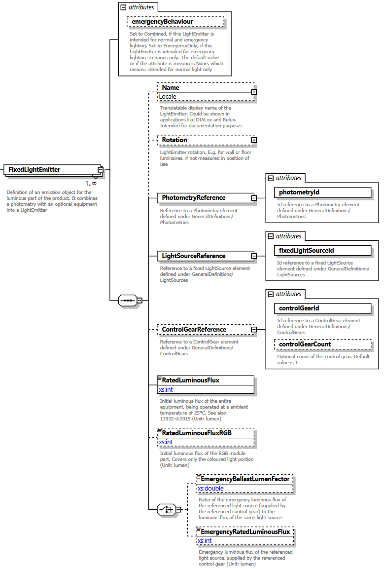
The main differences are:
- There is no
Equipmentreference anymore, since equipments represent a changeable construct of a lighting part in a luminaire. And therefore there is no possibility to reference aChangeableLightSourceanymore - Instead you have to define a
FixedLightSourcefirst. And reference it inside theFixedLightEmitterthrough aLightSourceReferenceelement and thefixedLightSourceIdattribute:
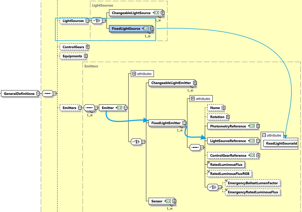
- Since the usual way of defining a ballast via
Equipmentis no longer possible, it can now also be referenced directly at theFixedLightEmitter➜ seeControlGearReferenceelement - The luminous flux of fixed lamps is logically no longer variable and must therefore also be specified directly on the
FixedLightEmitterelement ➜ seeRatedLuminousFluxandRatedLuminousFluxRBGelements - This also applies to any impact of the ballast on the luminous flux ➜ see
EmergencyBallastLumenFactorandEmergencyRatedLuminousFluxelements
Mandatory data example
Now let's define some FixedLightEmitter. Again, the simplest one first, with only mandatory data:
<?xml version="1.0" encoding="UTF-8"?>
<Root xmlns:xsi="http://www.w3.org/2001/XMLSchema-instance">
  <Header/>
  <GeneralDefinitions>
    <Files>
      <File id="ldcFile" contentType="ldc/eulumdat" type="localFileName">MyNarrowLvk.ldt</File>
    </Files>
    <Photometries>
      <Photometry id="photometryNarrow">
        <PhotometryFileReference fileId="ldcFile"/>
      </Photometry>
    </Photometries>
    <LightSources>
      <FixedLightSource id="ledModule_RGB">
        <Name>
          <Locale language="en">RGB dimmable</Locale>
          <Locale language="de">RGB dimmbar</Locale>
        </Name>
        <RatedInputPower>50</RatedInputPower>
      </FixedLightSource>
    </LightSources>
    <Emitters>
      <Emitter id="emitterNarrow">
        <FixedLightEmitter>
          <PhotometryReference photometryId="photometryNarrow"/>
          <LightSourceReference fixedLightSourceId="ledModule_RGB"/>
          <RatedLuminousFlux>450</RatedLuminousFlux>
        </FixedLightEmitter>
      </Emitter>
    </Emitters>
  </GeneralDefinitions>
  <ProductDefinitions/>
</Root>
Particularly noteworthy are
- Line 6: A
Filereference to an Eulumdat photometry file named MyNarrowLvk.ldt (located inside the GLDF Container) - Line 9: A
Photometryelement referencing the photometry file through thefileIdattribute - Line 14: A
FixedLightSourcewith an input power of 50 W - Line 24: The final
FixedLightEmitterwith- Line 25: A reference to the
Photometrythrough thephotometryIdattribute - Line 26: A reference to the
FixedLightSourcethrough thefixedLightSourceIdattribute - Line 27: A
RatedLuminousFluxelement saying, this combination emits 450 lumen
- Line 25: A reference to the
Complete data example
A complete FixedLightEmitter example adds an additional ballast, which shouldn't be required in most cases. And some data for emergency lighting scenarios, should the luminaire support them:
<?xml version="1.0" encoding="UTF-8"?>
<Root xmlns:xsi="http://www.w3.org/2001/XMLSchema-instance">
  <Header/>
  <GeneralDefinitions>
    <Files>
      <File id="ldcFile" contentType="ldc/eulumdat" type="localFileName">MyNarrowLvk.ldt</File>
    </Files>
    <Photometries>
      <Photometry id="photometryNarrow">
        <PhotometryFileReference fileId="ldcFile"/>
      </Photometry>
    </Photometries>
    <LightSources>
      <FixedLightSource id="ledModule_RGB">
        <Name>
          <Locale language="en">RGB dimmable</Locale>
          <Locale language="de">RGB dimmbar</Locale>
        </Name>
        <RatedInputPower>50</RatedInputPower>
      </FixedLightSource>
    </LightSources>
    <ControlGears>
      <ControlGear id="electronicControlGear">
        <!-- Content skipped for clarity -->
      </ControlGear>
    </ControlGears>
    <Emitters>
      <Emitter id="emitterNarrow">
        <FixedLightEmitter>
          <PhotometryReference photometryId="photometryNarrow"/>
          <LightSourceReference fixedLightSourceId="ledModule_RGB"/>
          <ControlGearReference controlGearId="electronicControlGear" />
          <RatedLuminousFlux>400</RatedLuminousFlux>
          <RatedLuminousFluxRGB>200</RatedLuminousFluxRGB>
          <EmergencyBallastLumenFactor>0.1</EmergencyBallastLumenFactor>
        </FixedLightEmitter>
      </Emitter>
    </Emitters>
  </GeneralDefinitions>
  <ProductDefinitions/>
</Root>
Compared to the first example, the following optional elements have been added:
- Line 23/32: A
ControlGearand aControlGearReferencewith the correspondingcontrolGearIdattribute - Line 34: An
RatedLuminousFluxRGBelement to declare the flux of the colored light only (the RGB module part) - Line 35: An additional
EmergencyBallastLumenFactor. Its the ratio of the emergency luminous flux to the total luminous flux specified byRatedLuminousFlux. You can replace it with anEmergencyRatedLuminousFluxelement instead, if an absolute flux value in emergency mode suits more.
Add these additional elements as applicable.
MultiChannelLightEmitter
The third emitter type is intended for light outputs of luminaires with multiple channels. It is also the simplest of the three, as the properties of the different channels are defined at the MultiChannelLightSource. In addition to the reference of a MultiChannelLightSource, the specification of a ControlGear is also possible, as well as the Emitter rotation (see below) and the Emitters display name.
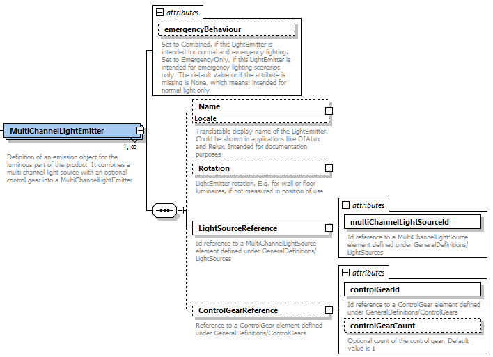
MultiChannelLightEmitter XML example
An example of the MultiChannelLightEmitter illustrates well how the definition of the channels happens at the MultiChannelLightSource itself - in particular the photometry and spectrum of each channel:
<?xml version="1.0" encoding="UTF-8"?>
<Root xmlns:xsi="http://www.w3.org/2001/XMLSchema-instance">
  <Header/>
  <GeneralDefinitions>
    <Files>
      <File id="photometryRedFile" contentType="ldc/eulumdat"
            type="url">http://example.org/photometryRed.ldt</File>
      <File id="photometryGreenFile" contentType="ldc/eulumdat"
            type="url">http://example.org/photometryGreen.ldt</File>
      <File id="photometryBlueFile" contentType="ldc/eulumdat"
            type="url">http://example.org/photometryBlue.ldt</File>
      <File id="spectrumRedFile" contentType="spectrum/text"
            type="url">http://example.org/spectrumRed.txt</File>
      <File id="spectrumGreenFile" contentType="spectrum/text"
            type="url">http://example.org/spectrumGreen.txt</File>
      <File id="spectrumBlueFile" contentType="spectrum/text"
            type="url">http://example.org/spectrumBlue.txt</File>
      <File id="lightSourceImage" contentType="image/jpg"
            type="url">http://example.org/image.jpg</File>
    </Files>
    <Photometries>
      <Photometry id="photometryRed">
        <PhotometryFileReference fileId="photometryRedFile"/>
      </Photometry>
      <Photometry id="photometryGreen">
        <PhotometryFileReference fileId="photometryGreenFile"/>
      </Photometry>
      <Photometry id="photometryBlue">
        <PhotometryFileReference fileId="photometryBlueFile"/>
      </Photometry>
    </Photometries>
    <Spectrums>
      <Spectrum id="spectrumRed">
        <SpectrumFileReference fileId="spectrumRedFile"/>
      </Spectrum>
      <Spectrum id="spectrumGreen">
        <SpectrumFileReference fileId="spectrumGreenFile"/>
      </Spectrum>
      <Spectrum id="spectrumBlue">
        <SpectrumFileReference fileId="spectrumBlueFile"/>
      </Spectrum>
    </Spectrums>
    <LightSources>
      <MultiChannelLightSource id="multiChannelLightSource">
        <Name>
          <Locale language="en">RGB MultiChannel</Locale>
        </Name>
        <RatedInputPower>50</RatedInputPower>
        <LightSourceImages>
          <Image fileId="lightSourceImage" imageType="Product Picture"/>
        </LightSourceImages>
        <Channels>
          <Channel type="Red">
            <DisplayName>
              <Locale language="en">Red</Locale>
            </DisplayName>
            <SpectrumReference spectrumId="spectrumRed"/>
            <PhotometryReference photometryId="photometryRed"/>
            <RatedLuminousFlux>150</RatedLuminousFlux>
          </Channel>
          <Channel type="Green">
            <DisplayName>
              <Locale language="en">Green</Locale>
            </DisplayName>
            <SpectrumReference spectrumId="spectrumGreen"/>
            <PhotometryReference photometryId="photometryGreen"/>
            <RatedLuminousFlux>150</RatedLuminousFlux>
          </Channel>
          <Channel type="Blue">
            <DisplayName>
              <Locale language="en">Blue</Locale>
            </DisplayName>
            <SpectrumReference spectrumId="spectrumBlue"/>
            <PhotometryReference photometryId="photometryBlue"/>
            <RatedLuminousFlux>150</RatedLuminousFlux>
          </Channel>
        </Channels>
      </MultiChannelLightSource>
    </LightSources>
    <ControlGears>
      <ControlGear id="controlGear">
        <Name>
          <Locale language="en">Electronic ballast</Locale>
        </Name>
        <NominalVoltage>
          <VoltageRange>
            <Min>220</Min>
            <Max>230</Max>
          </VoltageRange>
        </NominalVoltage>
        <StandbyPower>5</StandbyPower>
        <Dimmable>true</Dimmable>
        <ColorControllable>true</ColorControllable>
      </ControlGear>
    </ControlGears>
    <Emitters>
      <Emitter id="emitter">
        <MultiChannelLightEmitter>
          <LightSourceReference multiChannelLightSourceId="multiChannelLightSource"/>
          <ControlGearReference controlGearId="controlGear"/>
        </MultiChannelLightEmitter>
      </Emitter>
    </Emitters>
  </GeneralDefinitions>
  <ProductDefinitions/>
</Root>
SensorEmitter
The SensorEmitter is the simplest form of an Emitter. And as the name suggests, it is not intended for light sources, but for the definition of radiation-emitting parts in form of a Sensor:
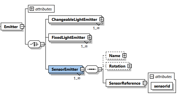
The XML example is correspondingly simple:
<?xml version="1.0" encoding="UTF-8"?>
<Root xmlns:xsi="http://www.w3.org/2001/XMLSchema-instance">
  <Header/>
  <GeneralDefinitions>
    <Files>
      <File id="sensorFile" contentType="sensor/sensldt"
            type="localFileName">ir_sensor.txt</File>
    </Files>
    <Sensors>
      <Sensor id="sensor1">
        <SensorFileReference fileId="sensorFile"/>
      </Sensor>
    </Sensors>
    <Emitters>
      <Emitter id="sensorEmitter">
        <SensorEmitter>
          <SensorReference sensorId="sensor1"/>
        </SensorEmitter>
      </Emitter>
    </Emitters>
  </GeneralDefinitions>
  <ProductDefinitions/>
</Root>
- Line 6: A
Filereference to a sensor file named ir_sensor.txt (located inside the GLDF Container) - Line 10: A
Sensordefinition referencing the sensor file through thefileIdattribute - Line 16: A
SensorEmitterdefinition referencing the sensor through thesensorIdattribute
Emitter Rotation
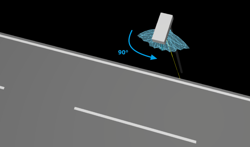
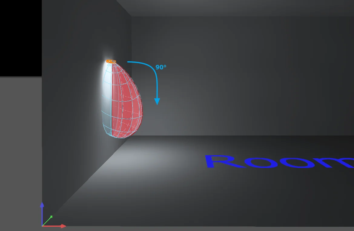
One element we haven't covered yet is the Rotation on each of the Emitter types. However, this is only needed for edge cases. The two most common are
-
IES 90° rotation around G0 for street luminaires
-
Wall luminaires not measured in their position of usage
Rotation XML Example
<?xml version="1.0" encoding="UTF-8"?>
<Root xmlns:xsi="http://www.w3.org/2001/XMLSchema-instance">
  <Header/>
  <GeneralDefinitions>
    <Files>
      <File id="streetLdcFile" contentType="ldc/ies" type="localFileName">street.ies</File>
    </Files>
    <Photometries>
      <Photometry id="streetPhotometry">
        <PhotometryFileReference fileId="streetLdcFile"/>
      </Photometry>
    </Photometries>
    <Emitters>
      <Emitter id="emitterWithRotation">
        <ChangeableLightEmitter>
          <Rotation>
            <X>0</X>
            <Y>0</Y>
            <Z>0</Z>
            <G0>90</G0>
          </Rotation>
          <PhotometryReference photometryId="streetPhotometry"/>
        </ChangeableLightEmitter>
      </Emitter>
    </Emitters>
  </GeneralDefinitions>
  <ProductDefinitions/>
</Root>