Control Gears
ControlGear Description
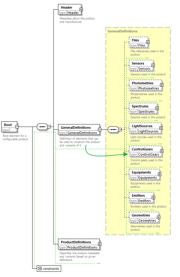
ControlGears is the sixth child-element of GeneralDefinitions - the part in the XML where global and reusable elements are defined (imagine them as the building blocks of each luminaire).
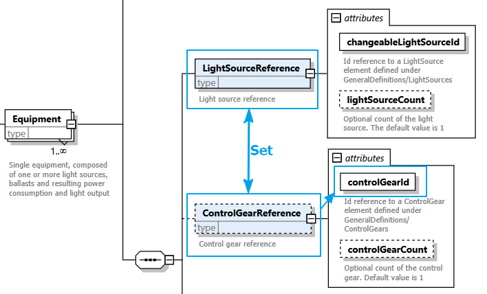
Control gears primarily usage is to depict luminaires with classic lamps (i.e. not LEDs) and - once definied - can be referenced in Equipments later on. There they can be one part of a set of a classical lamp and its corresponding control gear:
Location in XSD
XSD description
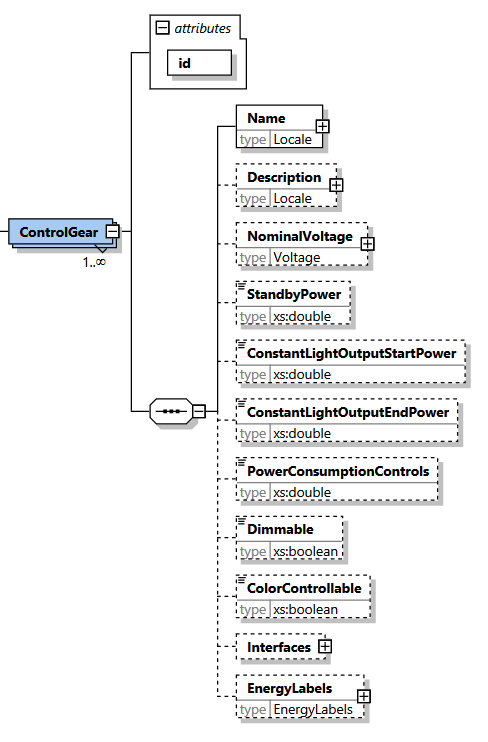
In addition to the mandatory id attribute and Name element, ControlGears can contain various additional metadata. However, the whole definition of control gears is optional.
XML example
Below you can find an example definition of two control gears:
<?xml version="1.0" encoding="UTF-8"?>
<Root xmlns:xsi="http://www.w3.org/2001/XMLSchema-instance"
      xsi:noNamespaceSchemaLocation="https://gldf.io/xsd/gldf/1.0.0-rc.3/gldf.xsd">
  <Header/>
  <GeneralDefinitions>
    <ControlGears>
      <ControlGear id="controlGear1">
        <Name>
          <Locale language="en">Some control gear of this luminaire</Locale>
          <Locale language="de">Ein Steuergerät dieser Leuchte</Locale>
        </Name>
      </ControlGear>
      <ControlGear id="controlGear2">
        <Name>
          <Locale language="en">Some other control gear of this luminaire</Locale>
          <Locale language="de">Ein weiteres Steuergerät dieser Leuchte</Locale>
        </Name>
      </ControlGear>
    </ControlGears>
  </GeneralDefinitions>
  <ProductDefinitions/>
</Root>
Each ControlGear element contains only the mandatory id attribute and Name element. The Name in this example is provided in two languages (de and en for German and English), but one translation is always sufficient in GLDF. These ControlGear
- can be referenced in subsequent elements via controlGear1 and controlGear2 (
idattribute, line 6 and 12) - provide no optional metadata (see below)
Referencing a control gear
Once declared, all control gears can be referenced in subsequent XML elements via their id attribute one or several times.
<?xml version="1.0" encoding="UTF-8"?>
<Root xmlns:xsi="http://www.w3.org/2001/XMLSchema-instance"
      xsi:noNamespaceSchemaLocation="https://gldf.io/xsd/gldf/1.0.0-rc.3/gldf.xsd">
  <Header>
    <!-- Content skipped for clarity -->
  </Header>
  <GeneralDefinitions>
  <LightSources>
    <ChangeableLightSource id="lightSource1">
      <!-- Content skipped for clarity -->
    </ChangeableLightSource>
  </LightSources>
  <ControlGears>
    <ControlGear id="controlGear1">
      <Name>
        <Locale language="en">Some control gear of this luminaires</Locale>
        <Locale language="de">Ein Steuergerät dieser Leuchte</Locale>
      </Name>
    </ControlGear>
  </ControlGears>
  <Equipments>
    <Equipment id="equipment1">
      <LightSourceReference changeableLightSourceId="lightSource1" />
      <ControlGearReference controlGearId="controlGear1" />
      <RatedInputPower>100</RatedInputPower>
    </Equipment>
  </Equipments>
  </GeneralDefinitions>
  <ProductDefinitions>
    <!-- Content skipped for clarity -->
  </ProductDefinitions>
</Root>
In the example above, the ControlGear with id controlGear1 (line 11) is referenced once inside the element Equipment and defines the luminaire's set of lamp and control gear (line 20/21).
ControlGear MetaData
It is possible to optionally specify various metadata inside a control gear to complement its description with further details:
<?xml version="1.0" encoding="UTF-8"?>
<Root xmlns:xsi="http://www.w3.org/2001/XMLSchema-instance"
  xsi:noNamespaceSchemaLocation="https://gldf.io/xsd/gldf/1.0.0-rc.3/gldf.xsd">
  <Header>
    <!-- Content skipped for clarity -->
  </Header>
  <GeneralDefinitions>
    <ControlGears>
      <ControlGear id="controlGear1">
        <Name>
          <Locale language="en-us">Name of the cotrol gear</Locale>
        </Name>
        <Description>
          <Locale language="en-us">Description of the control gear</Locale>
        </Description>
        <NominalVoltage>
          <VoltageRange>
            <Min>120</Min>
            <Max>240</Max>
          </VoltageRange>
          <Type>AC</Type>
          <Frequency>50/60</Frequency>
        </NominalVoltage>
        <StandbyPower>12</StandbyPower>
        <ConstantLightOutputStartPower>20</ConstantLightOutputStartPower>
        <ConstantLightOutputEndPower>100</ConstantLightOutputEndPower>
        <PowerConsumptionControls>2</PowerConsumptionControls>
        <Dimmable>true</Dimmable>
        <ColorControllable>true</ColorControllable>
        <Interfaces>
          <Interface>KNX</Interface>
          <Interface>DMX</Interface>
        </Interfaces>
        <EnergyLabels>
          <EnergyLabel region="EU">A+</EnergyLabel>
          <EnergyLabel region="US">EnergyStar</EnergyLabel>
        </EnergyLabels>
      </ControlGear>
    </ControlGears>
  </GeneralDefinitions>
  <ProductDefinitions>
    <!-- Content skipped for clarity -->
  </ProductDefinitions>
</Root>
- Description
Description of the control gear - NominalVoltage
Nominal voltage at which the product operates normally - StandbyPower
Power consumption of the luminaire switched off. All electrical components including emergency and lighting controls have to be considered. Also known as Parasitic Power. See EN 15193-1:2017 (Unit: watt) - ConstantLightOutputStartPower
Constant Light Output start power (Unit: watt) - ConstantLightOutputEndPower
Constant Light Output end power (Unit: watt) - PowerConsumptionControls
Power consumption of the detector in idle state with the light switched off and without motion/presence detection (Unit: watt) - Dimmable
Determines if the luminaire is dimmable - ColorControllable
Determines if the color is controllable - Interfaces
Determines which communication or control interface is supported by the luminaire or sensing device. Possible values are:- DALI Broadcast
- DALI Addressable
- KNX
- 0-10V
- 1-10V
- 230V
- RF
- WiFi
- Bluetooth
- Inter-Connection
- DMX
- DMX/RDM
- EnergyLabels
List of energy efficiency labels of the control gear, per region