L3D Editor
Introduction
The L3D Editor is a web-based CAD application developed by DIAL/DIALux to create L3D models from Wavefront OBJ files. These L3Ds models can then be used for detailed visualisation of your own products in GLDF (see Geometry).
In this chapter, the graphical user interface will be explained first. You will learn how to import Wavefront OBJ files into your project. How to align and expand them with properties that are important for the GLDF. Such as light emitter, light emitting surfaces and connectors. And finally how to create and work with joints for adjustable luminaires.
User interface
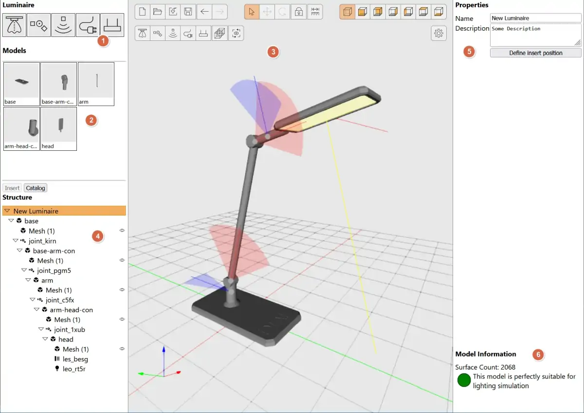
- Drag & Drop elements
In the upper left corner you can find various icons, which you can drag drop into the working CAD area (3). These are- LEO (Light Emitting Object) - this are the parts which GLDF
Emittercan be linked with. - Joints - this parts allow a hierachical and adjustable connection between two OBJs.
- Sensors - like LEOs but for sensor radiation, instead of light.
- Electrical connectors - define points on the geometry to mark electrical connections (cable entries/exits).
- Pendulum connectors - required for ceiling mounted luminaires to define points on the geometry, from which the luminaire is suspended.
- LEO (Light Emitting Object) - this are the parts which GLDF
- Import catalog
You can find your imported OBJ files here. And drag & drop them on the CAD working area (3). - CAD working area
The main working area of the application. You can place your objects here and position and rotate them. - Hierarchical view
Hierarchical view of all objects placed in the CAD view. Allows to select and enable/disable the visibility of objects. As well as their rearrangement in the hierarchy by drag & drop. - Property windows
Here you can set global project properties. As well as properties of selected objects in the CAD area. - Model information
Indication of the suitability of the constructed model for usage in light calculation applications such as DIALux and RELUX.
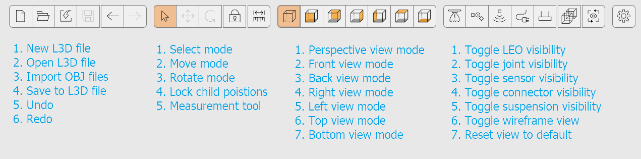
CAD area buttons
Most buttons in the CAD working area have tooltips with explanations. However, they should also be briefly introduced here:
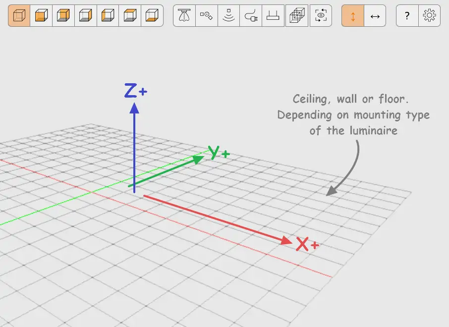
CAD area
The coordinate grid has a different meaning depending on the way the luminaire is mounted. And should be seen accordingly as ceiling, wall or floor. See model orientation for further details.
Model import
Only Wavefront OBJ files are supported and can be imported into the L3D Editor. There are three ways to import OBJ files:
- Via drag & drop of a file with the .obj extension to any position of the CAD working area (3)
- Using the Import button on top of the CAD working area
- Using the applications Catalog functionality:
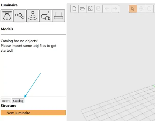
After the import, you should see your selected models on the left side with a small 3D preview:
Model scaling
Depending on the source application, models can be scaled differently. This can lead to geometries in the L3D Editor that are either far too large or far too small. Therefore, the editor allows scaling of the imported OBJs, during import and afterwards.
Scaling before import
If the scaling is already known before import, it can be set in advance. All models imported in the following will scale accordingly.
To do this, select the corresponding unit in the selection field of the Import Catalog.
Scaling after import
If the scaling is incorrect after the import, it can also be adjusted.
Simply open the Import Catalog and spycify the scaling as required for each model. Already placed OBJs in the CAD area will be scaled accordingly as well.
Model placement
Now that the OBJ models are imported into the application, they can be placed on the CAD surface. If this has not already been done by drag & drop during import, there are two ways to add OBJ models to the CAD working area:
- With the mouse via drag & drop from the Catalog to the CAD surface
- With the mouse via drag & drop from the Catalog to the hierarchy overview
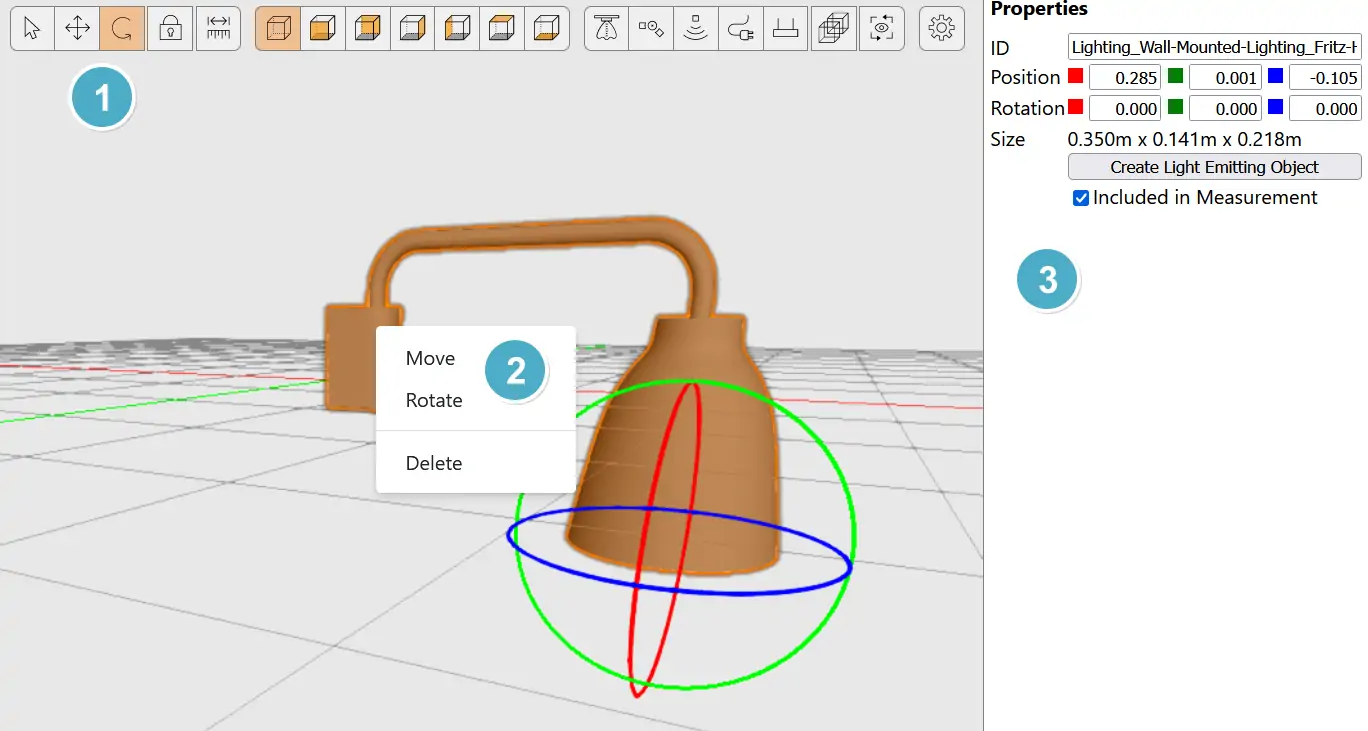
You can use the Move & Rotate modes (1) to translate your models. These modes are also accessible via context menu (2). Or use the property window to enter the values more precisely (3):
Model orientation
Once the model is placed, the question arises how to align it correctly inside the coordinate system. This depends on two factors:
- Alignment by mounting type
Is it a ceiling, wall or floor light? - Alignment by luminaire shape
Is it a symmetrical housing/light distribution or does it have a long side?
Floor surface/recessed
For floor luminaires, the coordinate plane represents the floor when placing the models. Note the following implications
- The camera angle on the coordinate system is already correctly aligned when opening the L3D Editor or reseting the view
- The mounting point of the luminaire should be placed at the origin X0, Y0, Z0
- If the luminaire is surface-mounted, it should face entirely upwards in Z+ axis
- If the luminaire is recessed into floor, only the visible part should be placed in Z+
- When creating the LEO and the luminaire has been measured in position of usage, the LEO G0 alignment has usually to be rotated by 180°, if the light output is facing upwards - see picture below
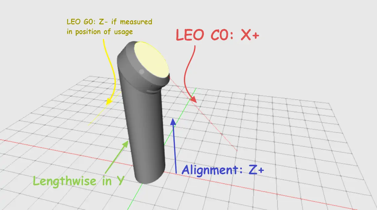
- Linear luminaires should be modelled along Y. C0 of the LEO should direct towards X+ - see picture below
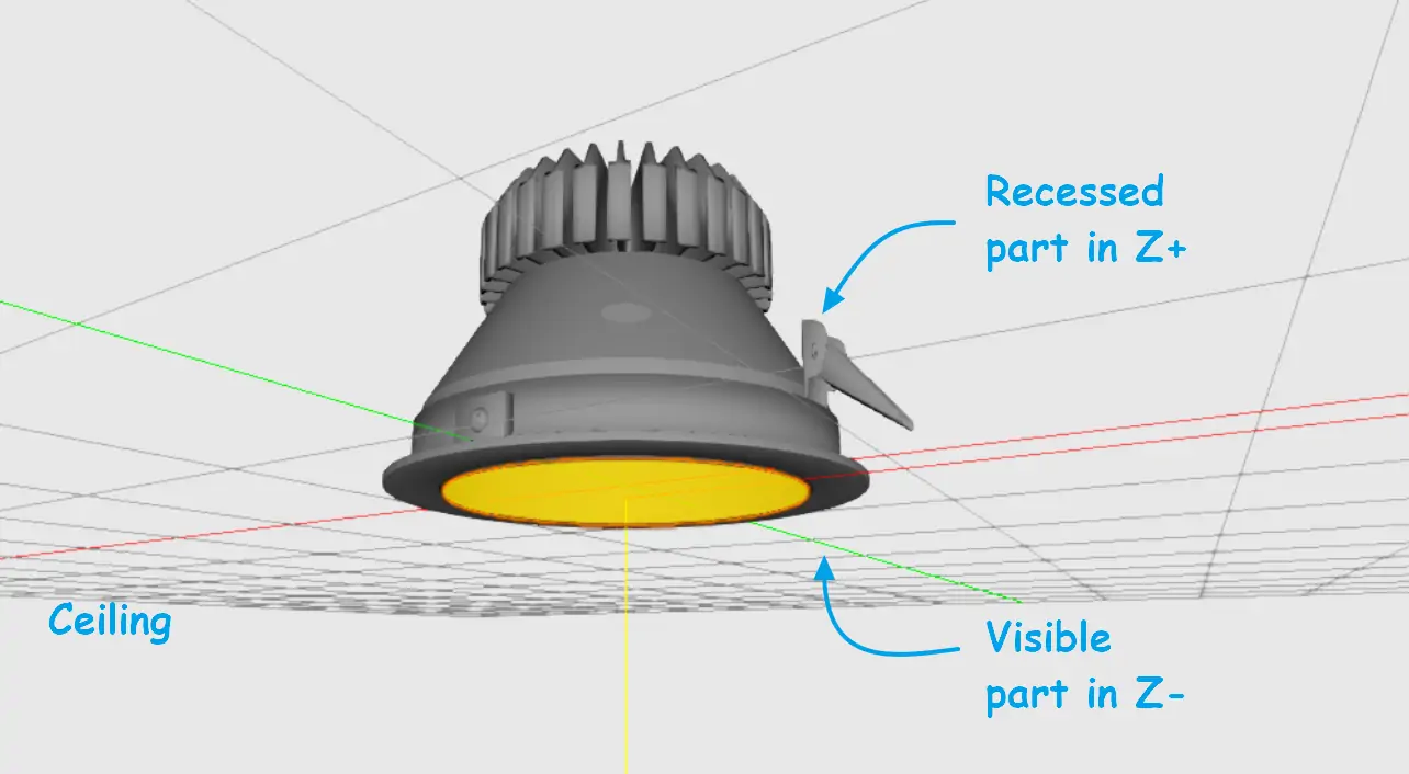
Ceiling surface/recessed
For ceiling luminaires, many things apply analogously to floor luminaires
- The coordinate plane is now to be considered as a ceiling
- The mounting point of the luminaire should be placed at the origin X0, Y0, Z0
- The visible part of the luminaire should face downwards in Z- axis
- Only the recessed part (if any) should be placed above the coordinate plane
- LEO G0 (yellow line) should direct to Z-, if the luminaire has been measured in position of usage
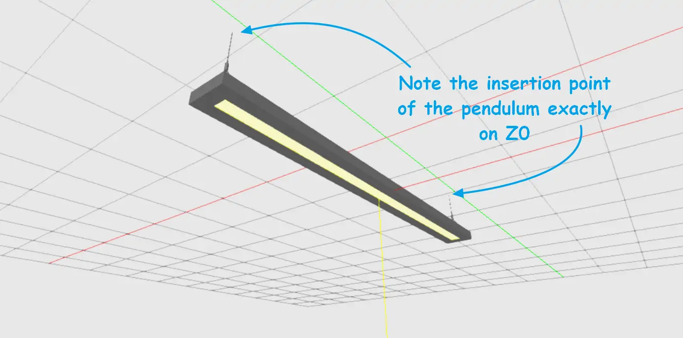
Ceiling pendant
There is one additional rule for pendant luminaires
- Pendant luminaires without modelled pendulum should be treated like ceiling-surface mounted luminaires; Don't model the pendulum gap between ceiling and luminaire! The pendulum length itself should be defined later in the GLDF
Variantelement (Mountingschild element) - Pendant luminaires with modelled pendulum should be placed accordingly to the image below. The Variant's
pendantLengthattribute in GLDF should be set to 0 in this case:
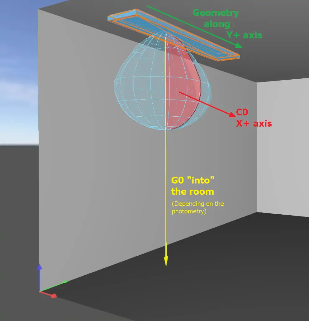
Wall surface/recessed
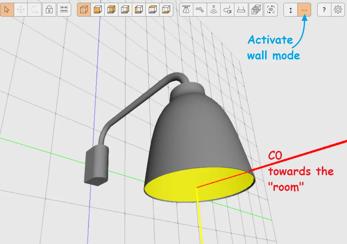
For wall-mounted luminaires, the L3D Editor offers a Wall luminaire mode. It rotates the coordinate plane by 90° without rotating the axis system - it's simply as visual helper. Using this mode, the following rules apply:
- The coordinate plane can now to be considered as a wall
- The mounting point of the luminaire should be placed at the origin X0, Y0, Z0
- Only the recessed part (if any) should be placed behind the coordinate plane "into the wall"
- LEO C0 should direct to X+ "into the room"
- Any mounting height can be set later in the GLDFs Variant's
Mountingschild element
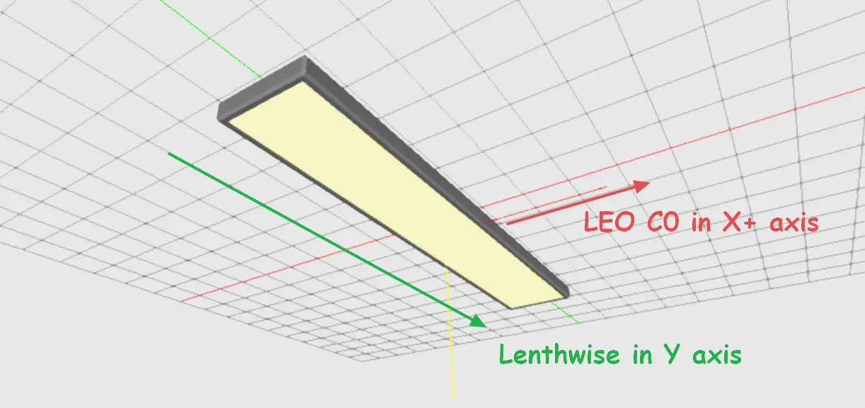
Alignment by luminaire shape
In addition to the mounting place, the luminaire shape must be taken into account while aligning your 3D models. This applies in particular to rectangular shaped luminaires with a long side.
- Linear luminaires must be aligned lengthwise to the Y axis
- LEO C0 should face X+
You can rotate the C0 plane by selecting the LEO and clicking on Rotate G0 Button (to rotate the C0 plane around the G0 axis)
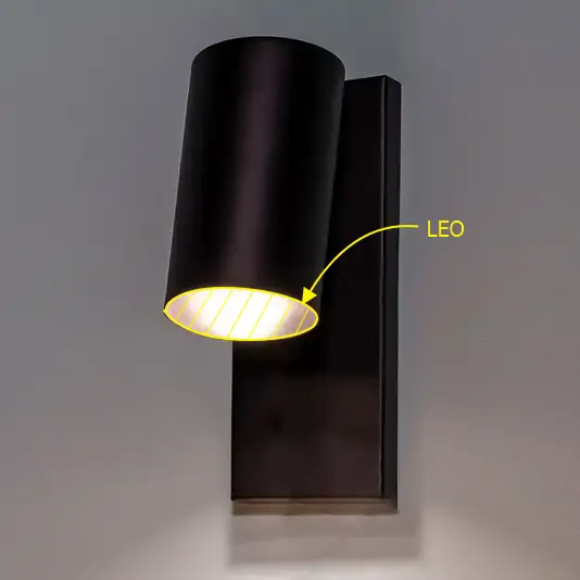
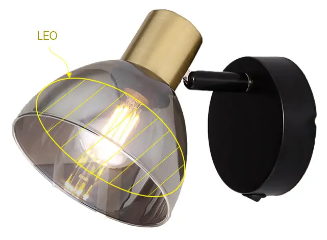
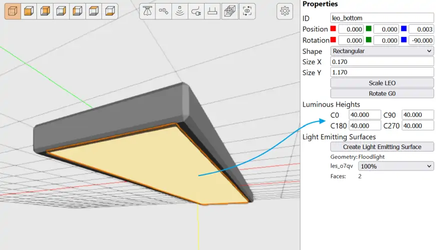
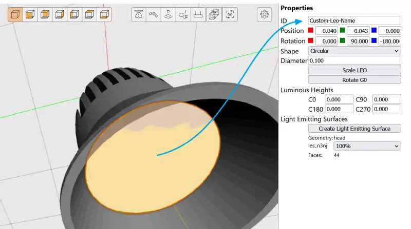
Light Emitting Objects (LEO)
Up to this point, the models imported, placed and oriented contain the geometric information for a luminaire now. For lighting calculation however, it is now necessary to determine which surfaces are luminous and therefore emit light. This is done using so-called Light Emitting Objects. Or LEO for short. After all, they are also the geometric connectors to the Emitter XML elements in the GLDF. The assignment of LEOs in the L3D model and the emitters in the GLDF is done via unique identifiers.
Creating a LEO
As with many functionalities in the L3D Editor, there are different ways to add a LEO to the luminaire model. One is to drag & drop the LEO onto the corresponding geometry in the CAD area. The model becomes highlighted in the scene and the LEO is hierarchically attached to the geometry:
Another way is to draw the LEO into the model. To do this, select the model and choose the corresponding surfaces:
Holding the Ctrl-key, you can undo selected areas.
Position, size & orientation
Since the LEO is a 2-dimensional surface, the question arises even more, how to scale, position and align it. This depends on a number of factors:
- the position of the light source inside the housing
- the translucency of the housing
- how the luminaire was measured in the lighting laboratory
Using an asymmetrical photometry, The LEO alignment is even more important.
LEO position
The LEO should always be positioned at the place of light emission - not necessarily of the light source. This may be the same position, but it does not have to be. This shall be clarified with the following example:
For a luminaire with an opaque housing, the LEO should be placed exactly at the light exit: Since this is also where the photometric measurement takes place:
For a luminaire with a transparent housing, on the other hand, the LEO should be placed at the height of the light source:
In addition, it should be taken into account that in light calculation applications like DIALux and RELUX, the photometry itself is placed exactly in the centre of the LEO.
LEO size
Even if the photometry is positioned exactly in the centre of the LEO, as written above, the LEO should not be defined as a point only. It should be defined as the actual luminous surface of the luminaire. The reason for this is, that this surface is also used in lighting design software for near-field calculation and UGR (Unified Glare Rating).
If a LEO is selected, it is also possible to specify the luminous heights. Usually these are taken from the photometric file, but can also be stored in the model in case they are missing or should be overwritten.
LEO orientation
To better illustrate the LEO alignment, two helper lines are permanently displayed as soon as a LEO is created:
- the yellow G0 plane line
- the red C0 plane line
C0 plane
Rule of thumb: lighting design software expect the geometry of the luminaire to be placed along the (green) Y-axis. While the C0 plane should point in the direction of the positive X-axis (or in other words be horizontally positive). This is highlighted in the editor by a short red line
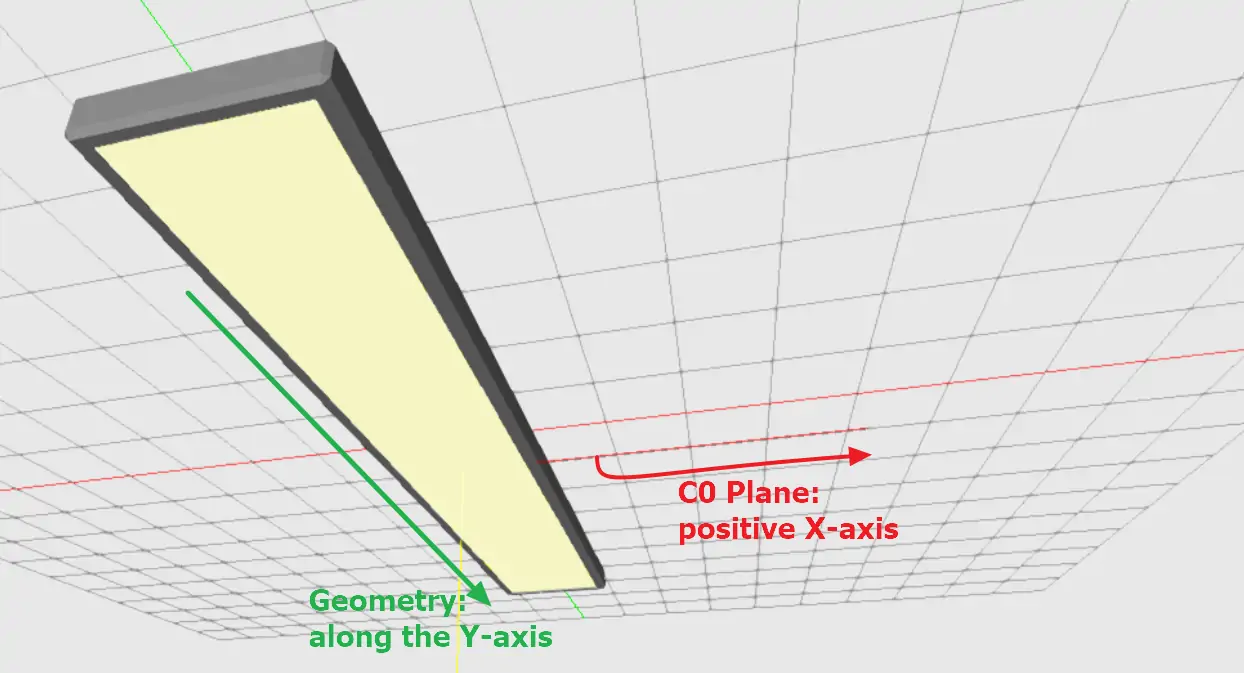
Yo can rotate the C0 plane by selecting the LEO and clicking on Rotate G0 Button (to rotate the C0 plane around the G0 axis)
A C0 rotation by 90° around G0 is often required for street luminaires with IES photometry.
G0 plane
The G0 plane defines the orientation of the photometry at the LEO and is visualised in the L3D editor by a short yellow line. The preferred G0 orientation is mainly influenced by two factors:
- Type of luminaire (ceiling, floor, wall)
- Position of the luminaire during the photometric measurement
Usually, G0 should point into the room by default. This means
- For ceiling luminaires into the negative Z axis
- For floor luminaires into the positive Z axis
- For wall luminaires it depends on housing, orientation and measurement
So if for some reason the luminaire has not been measured in the position of usage, this can be corrected by rotating the G0 plane.
Following these rules, the final model (within GLDF) should be rendered inside a room in DIALux and RELUX as follows:
LEO names & GLDF
Imagine a luminaire with two light emitting objects like this:
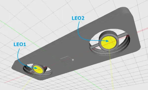
And let's further assume that they are differently equipped in terms of light. For example, a 10W narrow and a 15W wide beam spot. As a consequence, the final L3D model must be afterwards assigned different Emitter in the GLDF, that actually reflects these differences.
For this to be possible, the two different LEOs must be referenced from within the GLDF. And this is exactly what is done via unique LEO names. LEO names are automatically assigned in the L3D Editor as soon as a LEO is added. However, these are somehow cryptic and should be overwritten for better usability. Simply select the LEO in the CAD area or through the hierarchy on the left. And assign a new LEO name in the property area on the right side of the L3D Editor:
Referencing in GLDF
To continue the example with the two LEOs: On GLDF side, these LEO names are referenced in the Variant element, while joining Emitter and Geometry together. The Variant Element has a child element named ModelGeometryReference for this purpose:
<?xml version="1.0" encoding="UTF-8"?>
<Root xmlns:xsi="http://www.w3.org/2001/XMLSchema-instance"
      xsi:noNamespaceSchemaLocation="https://gldf.io/xsd/gldf/1.0.0-rc.3/gldf.xsd">
    <Header>
        <!-- Skipped for clarity -->
    </Header>
    <GeneralDefinitions>
        <Files>
            <File id="photometryFileNarrow" contentType="ldc/eulumdat"
                  type="localFileName">PhotometryNarrow.ldt</File>
            <File id="photometryFileWide" contentType="ldc/eulumdat"
                  type="localFileName">PhotometryWide.ldt</File>
            <File id="l3dModelFile" contentType="geo/l3d"
                  type="localFileName">geometry.l3d</File>
        </Files>
        <Photometries>
            <Photometry id="photometryNarrow">
                <PhotometryFileReference fileId="photometryFileNarrow"/>
            </Photometry>
            <Photometry id="photometryWide">
                <PhotometryFileReference fileId="photometryFileWide"/>
            </Photometry>
        </Photometries>
        <LightSources>
            <FixedLightSource id="fixedLightSource-10w">
                <Name>
                    <Locale language="en">LED module 10W</Locale>
                </Name>
                <RatedInputPower>10</RatedInputPower>
            </FixedLightSource>
            <FixedLightSource id="fixedLightSource-15w">
                <Name>
                    <Locale language="en">LED module 15W</Locale>
                </Name>
                <RatedInputPower>15</RatedInputPower>
            </FixedLightSource>
        </LightSources>
        <Emitters>
            <Emitter id="fixedEmitter-narrow">
                <FixedLightEmitter>
                    <PhotometryReference photometryId="photometryNarrow"/>
                    <LightSourceReference fixedLightSourceId="fixedLightSource-10w"/>
                    <RatedLuminousFlux>100</RatedLuminousFlux>
                </FixedLightEmitter>
            </Emitter>
            <Emitter id="fixedEmitter-wide">
                <FixedLightEmitter>
                    <PhotometryReference photometryId="photometryWide"/>
                    <LightSourceReference fixedLightSourceId="fixedLightSource-15w"/>
                    <RatedLuminousFlux>150</RatedLuminousFlux>
                </FixedLightEmitter>
            </Emitter>
        </Emitters>
        <Geometries>
            <ModelGeometry id="modelGeometry">
                <GeometryFileReference fileId="l3dModelFile" />
            </ModelGeometry>
        </Geometries>
    </GeneralDefinitions>
    <ProductDefinitions>
        <ProductMetaData>
            <!-- Skipped for clarity -->
        </ProductMetaData>
        <Variants>
            <Variant id="variant-1">
                <Name>
                    <Locale language="en">Example luminaire with L3D and multiple LEOs</Locale>
                </Name>
                <Geometry>
                    <ModelGeometryReference geometryId="modelGeometry">
                        <EmitterReference emitterId="fixedEmitter-narrow">
                            <EmitterObjectExternalName>LEO1</EmitterObjectExternalName>
                        </EmitterReference>
                        <EmitterReference emitterId="fixedEmitter-wide">
                            <EmitterObjectExternalName>LEO2</EmitterObjectExternalName>
                        </EmitterReference>
                    </ModelGeometryReference>
                </Geometry>
            </Variant>
        </Variants>
    </ProductDefinitions>
</Root>
The particular rows in the XML example are highlighted:
- First, the L3D
Filewith the two LEOs is referenced (13-14, see initial image above) - A
Geometryelement references the L3D model file (55) - Matching
Emitterare defined for the two LEOs (39 and 46) - And finally, in the
Variantthe geometry (70) is combined with the twoEmitter(71 and 74) using theModelGeometryReferenceelement. - In order to specify which emitter in GLDF should be assigned to which LEO in the L3D, the LEO names previously defined in the L3D editor are now set using
EmitterObjectExternalName(72 and 75).
Light Emitting Surface (LES)
Light Emitting Surfaces (LES) - similar to Light Emitting Objects (LEO) - are model surfaces with a special meaning. While LEOs are the surfaces that emit the photometrically measured light (The photometry is "placed" in their center). LES are meant for visualisation in applications like DIALux/Relux: They appear simply brighter.
- On surfaces marked as LEO the photometry is positioned in the center of them. They are intended for the physically correct calculation.
- Areas marked as LES have no relevance for the light calculation. They are only intended for visualisation of the luminaire.
- At least one LEO must be present in the model, otherwise it cannot be saved in the L3D editor. LES are optional on the other hand.
By default there is no need to create LES them manually. Whenever a LEO is created, a LES with a luminous intensity of 100% is also created for the corresponding areas. However, you can create them also manually. Simply select the LEO you would like to create an additional LES for. And click on Create Light Emitting Surface:
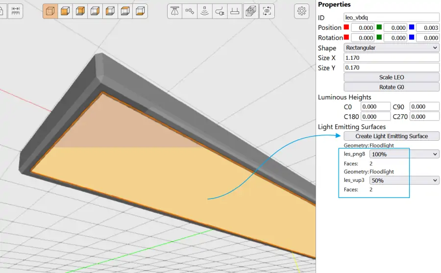
It is also possible to make some LES appear darker or lighter by setting the percentage to a value between 10% and 100%.
Joints
The L3D format as well as the L3D Editor support luminaires with movable Joints, which can then be adjusted for the respective lighting scene in applications such as DIALux and Relux.
In the L3D editor, these joints are separate objects that are placed in the CAD area. They create a hierarchy between two objects. Once placed, you can use the property window to set degrees of freedom, in which the user can later rotate the child object on the X, Y and/or Z axis:
Connectors
The L3D format supports also two types of connectors:
-
Electric connector
The electrical connctor marks inputs/exits for power cables and can be useful for planners and architects who need to take this into account in their plans. -
Pendulum connector
As the name suggests, the pendulum connector is only relevant for pendant luminaires. It marks the point(s) of the model, at which the luminaire should be visually suspended in applications like DIALux/Relux.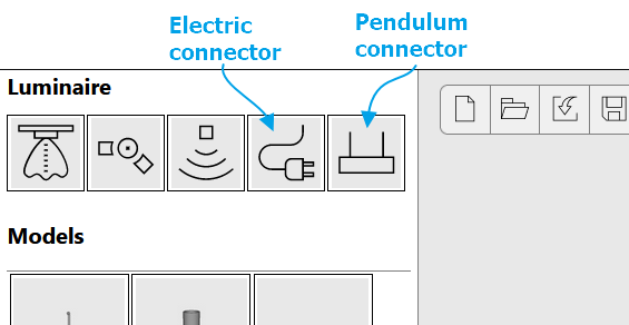
To add a connector to the model, simply drag & drop it onto the corresponding object in the CAD area or in the hierarchy overview: