L3D Examples
The source and .obj files of all examples can be downloaded from the L3D Github Repository
Example 1: Simple Cube Luminaire
(example_000): Assuming in the models directory is a cube.obj file available which contains a simple cube with the following data:
- Length: 0.5m
- Width: 0.25m
- Height: 0.1m
Example 1 Cube
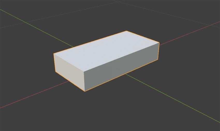
We want to add a LightEmittingObject at the bottom of the cube and create a luminaire with the insert point at the center of the bottom face.
The following example xml creates exactly what we want.
<?xml version="1.0" encoding="UTF-8"?>
<Luminaire xmlns:xsi="http://www.w3.org/2001/XMLSchema-instance"
  xsi:noNamespaceSchemaLocation="https://gldf.io/xsd/l3d/0.11.0/l3d.xsd">
  <Header>
    <CreatedWithApplication>Example-Tool</CreatedWithApplication>
    <CreationTimeCode>2021-03-03T10:10:10</CreationTimeCode>
    <FormatVersion major="0" minor="11" pre-release="0" />
  </Header>
  <GeometryDefinitions>
    <GeometryFileDefinition id="cube" filename="cube.obj" units="m" />
  </GeometryDefinitions>
  <Structure>
    <Geometry partName="luminaire">
      <Position x="0" y="0" z="0" />
      <Rotation x="0" y="0" z="0" />
      <GeometryReference geometryId="cube" />
      <LightEmittingObjects>
        <LightEmittingObject partName="leo">
          <Position x="0" y="0" z="0" />
          <Rotation x="0" y="0" z="0" />
          <Rectangle sizeX="0.5" sizeY="0.25" />
        </LightEmittingObject>
      </LightEmittingObjects>
      <LightEmittingSurfaces>
        <LightEmittingSurface partName="les">
          <LightEmittingObjectReference lightEmittingPartName="leo" />
          <FaceAssignments>
            <FaceAssignment faceIndex="3" />
          </FaceAssignments>
        </LightEmittingSurface>
      </LightEmittingSurfaces>
    </Geometry>
  </Structure>
</Luminaire>
Example 1 Cube Geometry
To reference the cube.obj file in the models directory, we need to create a GeometryFileDefinition] in the GeometryFileDefinition element and set the attributes. The id attribute can freely be chosen but must start with a letter and must be unique among all GeometryFileDefinition elements in the XML file. The filename has to be cube.obj without the models directory path. Sinse the cube.obj file coordinates are in meters, we neet to set the units attribute to m.
After that we can create a Geometry element in the Structure element. The partName also can be chosen freely but must be unique among all Geometry, Joint and LightEmittingObject elements, and must also start with a letter.
As we see the cube is already placed correctly, so we don't need any translation or rotation of the geometry in this example.
To tell that this geometry element has to use the cube.obj as gometry source, we need to create a reference to the defined GeometryFileDefinition. We do that by creating a GeometryReference element and set the geometryId attribute to the id we defined in the GeometryFileDefinition - cube.
Example 1 Light Emitting Object
To add a light emitting object to our luminaire we need to create a LightEmittingObject in the LightEmittingObjects element of the current geometry part. The partName attribute can freely be chosen just as in the Geometry element. The only difference ist that this name will be referenced by the GLDF-XML.
Initially the light emitting object will be placed relative to the parent geometry part. In this example the initial position is coincidentally at the right position.
The shape of the light emitting object can be rectangular or circular. To define the shape of the light emitting object we need to create a Rectangle or a Circle child element in our LightEmittingObject element. In this case the shape is rectangular, so we need to create a Rectangle element. Sinse the light emitting object corresponds to the whole bottom surface the attributes sizeX and sizeY equal the length and width of the cube.
Example 1 Light Emitting Surfaces
As the last step we have to indicate which of the cube surfaces/triangles should act as the light emitting surfaces. We know that the light emitting object is on the bottom of the cube so the bottom surface should act as light emitting surface too. In this cube the triangle indices of the bottom surface are 6 and 7.
To indicate that this two triangle should act as light emitting surface we need to create a LightEmittingFaceAssignments element with two Assignment child elements. Each for every triangle. The Assignment element needs the attributes faceIndex and lightEmittingPartName. faceIndex is the (zero based) triangle index in the model and the lightEmittingPartName is partName of the LightEmittingObject element this light emitting surface is related to.
In case you have many successive triangle indices you could also use the RangeAssignment element, which takes the attributes faceIndexBegin and faceIndexEnd instead of a single faceIndex.
Example 2: Cube Luminaire With Translated Parts
(example_001): Assuming in the models directory is a cube.obj file available which contains a simple cube with the following data:
- Length: 0.5m
- Width: 0.25m
- Height: 0.1m
Example 2 Cube
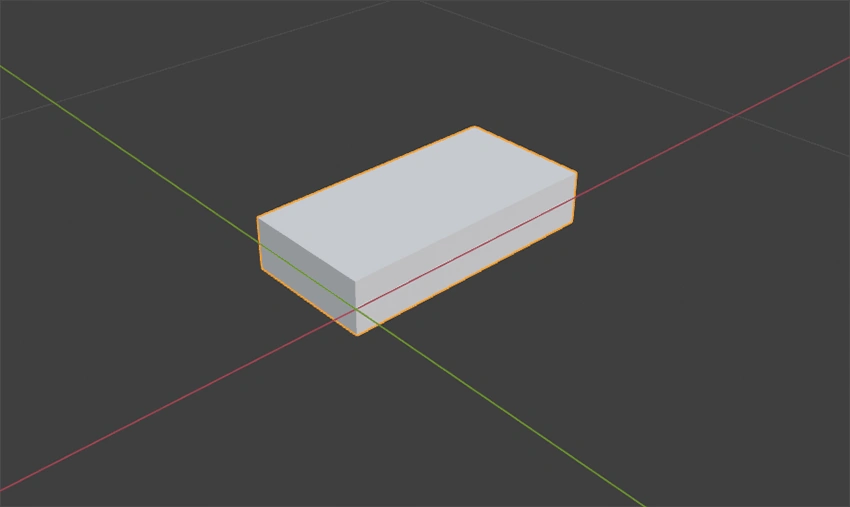
We want to create a luminaire with a light emitting object at the bottom of the luminaire. Just like in the previous example. The only difference is that this time the geometry doesn't align with the insert point. Here we have to make some adjustemnts in order to create the exact same luminaire as in the last example.
The xml below contains these adjustments.
<?xml version="1.0" encoding="UTF-8"?>
<Luminaire xmlns:xsi="http://www.w3.org/2001/XMLSchema-instance"
  xsi:noNamespaceSchemaLocation="https://gldf.io/xsd/l3d/0.11.0/l3d.xsd">
  <Header>
    <CreatedWithApplication>Example-Tool</CreatedWithApplication>
    <CreationTimeCode>2021-03-03T10:10:10</CreationTimeCode>
    <FormatVersion major="0" minor="11" pre-release="0" />
  </Header>
  <GeometryDefinitions>
    <GeometryFileDefinition id="cube" filename="cube.obj" units="m" />
  </GeometryDefinitions>
  <Structure>
    <Geometry partName="luminaire">
      <Position x="-0.25" y="-0.125" z="0.05" />
      <Rotation x="0" y="0" z="0" />
      <GeometryReference geometryId="cube" />
      <LightEmittingObjects>
        <LightEmittingObject partName="leo">
          <Position x="0.25" y="0.125" z="-0.05" />
          <Rotation x="0" y="0" z="0" />
          <Rectangle sizeX="0.5" sizeY="0.25" />
        </LightEmittingObject>
      </LightEmittingObjects>
      <LightEmittingSurfaces>
        <LightEmittingSurface partName="les">
          <LightEmittingObjectReference lightEmittingPartName="leo" />
          <FaceAssignments>
            <FaceAssignment faceIndex="3" />
          </FaceAssignments>
        </LightEmittingSurface>
      </LightEmittingSurfaces>
    </Geometry>
  </Structure>
</Luminaire>
Example 2 Cube Geometry
As we know the cube is not placed as we want it, so we need to correct that by moving the cube to the right position. We move the cube by minus half size in x and minus half size in y direction and up by half of its height. The model doesn't need any rotation, but the element is mandatory.
Example 2 Light Emitting Object
Initially the light emitting object will be placed relative to the parent geometry part. In this example the initial position would be in the corner of the cube (zero position), which is not what we want. In order to correct that we need to move the light emitting object to the correct position. Coincidentally the values to move the light emitting object are the negative values of the values we used for the geometry position.